Synchronize Azimuth Angle
1 Overview
Hesai lidar products support the "Sync Angle" feature, which controls the lidar to rotate to a specified azimuth at the whole second moment. This feature plays a critical role in achieving real-time angle and data synchronization between the lidar and other devices (e.g. cameras, radars and lidars), ensuring high precision and stability in multi-sensor perception systems.
2 Principle
Hesai lidar defines its azimuth position and applies closed-loop control on its motor speed and phase to ensure that its azimuth points to the preset direction at every whole second moment, achieving the synchronization to the reference signal.
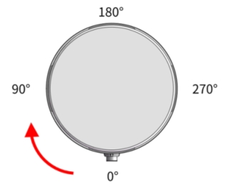
- For mechanical rotating lidar products (with a horizontal FOV of 360°, including models such as the Pandar series/QT series/XT series), the azimuth position definition can be referenced in the diagram below (XT32 - top view): 0° corresponds to the direction of lidar's cable outlet, 180° corresponds to the front direction. Within the default clockwise rotation of 360°, any azimuth within the 360° range can be configured as the sync angle value.
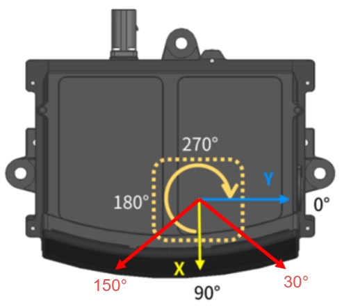
- For the model of AT128P with a horizontal FOV of less than 360° (achieving one-dimensional horizontal scanning via internal rotating mirrors), the azimuth position definition of its point cloud differs from mechanical rotating lidar products. As shown in the diagram below, the front direction of the lidar is defined as 90°, the horizontal FOV boundaries are defined as 30° and 150° at both sides, corresponding to a horizontal FOV of 120°. Therefore, the range of sync angle values that can be set is 30°~150°.
Considering the actual frame rate configuration of Hesai lidar products, the lidar operates at a cycle of either 100 ms (corresponding to a 10Hz frame rate) or 50 ms (corresponding to a 20Hz frame rate) to rotate to the configured sync angle, ensuring that each frame of data achieves angle synchronization.
In multi-sensor systems that include lidars, the critical prerequisite for achieving angle synchronization is that these sensors must be time-synchronized using the same external clock source. For Hesai lidars, time synchronization can be achieved using the following two methods:
- PTP time synchronization: This synchronization method defines the whole second by the whole second timestamp sent by the PTP master.
- GPS time synchronization: This synchronization method defines the whole second by the rising edge of the PPS (pulse per second) signal input to the lidar (only some Hesai lidar models support GPS time synchronization).
Note: If this feature is enabled without executing time synchronization, Hesai lidar will still use its internal clock PPS signal's rising edge to synchronize its azimuth output. However, due to differences in internal clocks between sensors, accurate angle synchronization between each sensors cannot be achieved.
3 Application Method
The method to use the sync angle feature is introduced as follows:
-
Establish time synchronization: Synchronize the lidar with an external clock source, such as using the PTP method (specific methods are detailed in Synchronize Time using PTP).
-
Configure sync angle parameters: Configure parameters related to sync angle, including whether to enable sync angle and the exact angle value to specify the preset angle that the lidar needs to point to.
Hesai lidar supports the following methods to configure angle synchronization parameters:
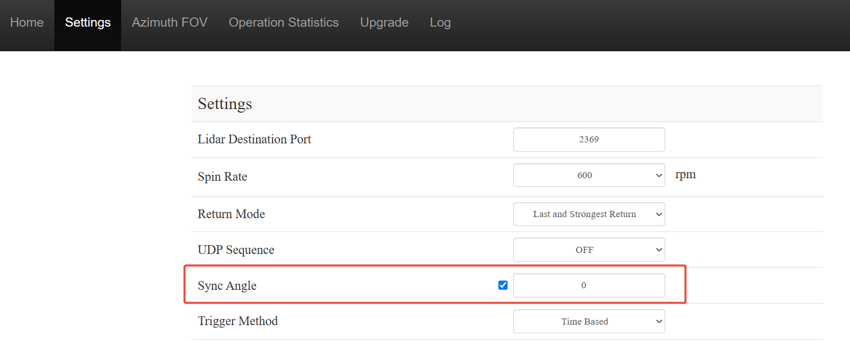
- Web control page (applicable to Pandar series/QT series/XT series models)
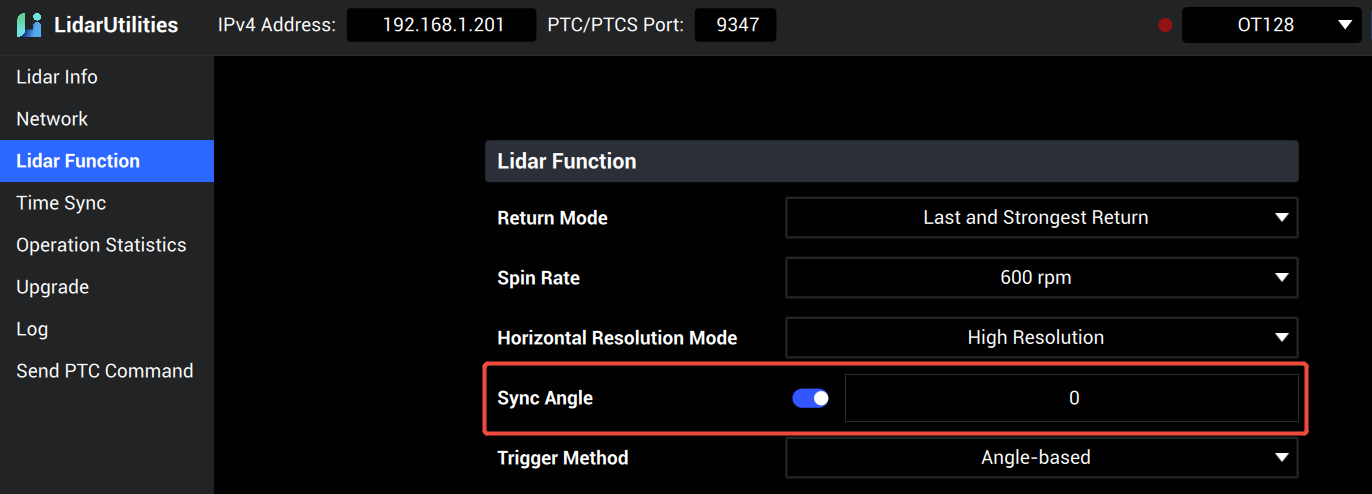
- LidarUtilities software (applicable to OT128/AT128P models)
Note: LidarUtilities can be downloaded from Hesai's official website (OT128,AT128P).
- HTTP API (using XT32 as example)
HTTP://<IP>/pandar.cgi?action=set&object=lidar_sync&key=sync_angle&value=<VALUE>
The VALUE parameter configuration is as follows:
{
"sync": 1,
"syncAngle": 0
}
Here, 'sync' indicates whether angle synchronization is enabled, 0 means disabled (default) and 1 means enabled; 'syncAngle' indicates the sync angle value in degrees, ranging from 0~359 (default value is 0).
Note: For detailed using method of HTTP API, refer to Use HTTP API.
- TCP API (using XT32 as example)
Send the following TCP API command to the lidar:
Command name: Set Sync Angle; Command code: 0x18;
Command Payload: First data field 'sync_enable' indicates the sync angle status (0-disabled, 1-enabled); second data field 'sync_angle' indicates the sync angle value, ranging from 0~359 (default value is 0).
Note: For detailed using method of TCP API, refer to Use TCP API.
4 Application Cases
4.1 Multi-Sensor Angle Synchronization
In autonomous driving solutions, it is often necessary for multiple lidar sensors on the same vehicle to simultaneously point to the front of the vehicle to ensure they can capture the same environmental information. However, since these lidars are usually installed in different positions, the hardware connector direction (i.e., the 0° direction of the lidar itself) also differs. By enabling sync angle and setting the corresponding angle values, all lidars can point tp the same direction at the same time after time synchronization, which could improve the data accuracy and consistency.
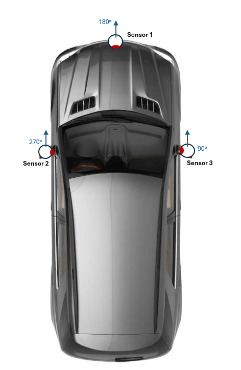
As shown in the diagram:
- lidar #1's 180° direction points to the front of the vehicle;
- lidar #2's 270° direction points to the front of the vehicle;
- lidar #3's 90° direction points to the front of the vehicle;
Thus, the sync angle configuration for these three lidars should be set to 180°, 270°, and 90°, respectively.
4.2 Anti-Interference between lidars
See the scenario illustrated in the diagram below, when two lidars are installed very close to each other on the same vehicle, there will be a high probability of severe mutual interference, resulting in a large number of noise points and data quality degradation.
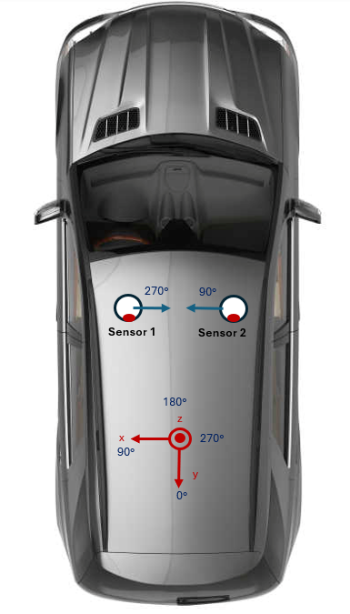
For such scenarios, the best solution is to place physical barriers between the two lidars to eliminate mutual interference. However, when this solution is not feasible in practice, the sync angle feature can still be used to resolve this issue: Considering that interference usually occurs when the laser emitted by one lidar is received by the other lidar, through proper sync angle settings the two lidars can only point to each other within a limited azimuth range (i.e. mutual shooting zone), and by setting the effective FOV range of both lidars to finally avoid them emitting lasers in the mutual shooting zone. The specific operation process is as follows:
-
Synchronize the two lidars to the same clock source;
-
Configure sync angle values. Based on the scenario in the diagram above, when the connector directions of these two lidars are consistent and both point to the rear of the vehicle, the synchronization angle for lidar #1 (left side) can be set to 270°, and the synchronization angle for lidar #2 (right side) can be set to 90°, achieving mutual shooting at a specific moment;
-
Set the effective horizontal FOV range. The affected azimuth range 𝜃𝑠 during mutual shooting can be calculated using the following formula:
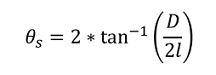
In the formula, 𝐷 is the lidar diameter, and 𝑙 is the distance between the two lidars. Using the XT32 model and the scenario shown in the diagram below, when the centers of the two lidars are 1m apart, the calculated invalid angle range 𝜃𝑠 is approximately 6°:
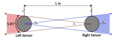
From the results in this diagram, the effective FOV range for these two lidars can be set to the azimuth range outside the corresponding sync angle value ± 5° (with some FOV setting margin reserved), ensuring that both lidars only emit lasers within the following FOV ranges:
- lidar #1: 275°~265°
- lidar #2: 95°~85°
Note: The rotation direction of both lidars is the default clockwise rotation.
Find it useful?